Vitodens 242-F B2UA 3.2 to 26 kW
Vitodens 242-F B2UA 3.2 to 26 kW
| ID | Parts Number | Part Description | Notes | Purchase |
|---|---|---|---|---|
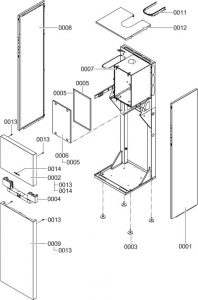
| 1 | Side panel, right | |||
| 2 | Front panel, top | |||
| 3 | Adjustable foot | |||
| 4 | Control unit support | |||
| 5 | Profiled seal | |||
| 6 | Cover panel with profiled seal | |||
| 7 | Toggle fastener (4 pce) | |||
| 8 | Side panel, left | |||
| 9 | Front panel, bottom | |||
| 10 | Retaining clip | |||
| 11 | Top panel insert | |||
| 12 | Top panel | |||
| 13 | Fixings for location stud (2 pce) | |||
| 14 | Logo | |||
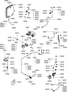
| 1 | Hydraulic block | |||
| 2 | Set of plug-in connector retainers (2 pce) | |||
| 3 | Diaphragm grommet (5 pce) | |||
| 4 | Diaphragm grommet (5 pce) | |||
| 5 | Clip Ø 8 (5 pce) | |||
| 6 | Clip Ø 10 (5 pce) | |||
| 7 | Clip Ø 15 (5 pce) | |||
| 8 | Clip Ø 18 (5 pce) | |||
| 9 | Air vent valve G3/8 | |||
| 10 | Spring clip (5 pce) | |||
| 11 | Connection pipe HR | |||
| 12 | Pipe clip Ø 18 / 1.5 | |||
| 13 | Fascia ? 13-19 kW Ø 4.0 (white) ? 26 kW Ø 5.5 (dark grey) | |||
| 14 | Pipe clip Ø 18 | |||
| 15 | Union nut G1 | |||
| 16 | Sleeve | |||
| 17 | Connection pipe, heating water flow | |||
| 18 | Connection pipe, DHW | |||
| 19 | Connection pipe, cold water, cylinder (130 l) | |||
| 20 | Expansion vessel connection line G 3/8 | |||
| 21 | Cold water hydraulic connection | |||
| 22 | Pump motor | |||
| 23 | CIL casing | |||
| 24 | Cartridge non-return valve | |||
| 25 | Shut-off valve, cold water, cylinder | |||
| 26 | Circular seal washer 8 x 2 (5 pce) | |||
| 27 | Connection line, DHW charging | |||
| 28 | Shut-off valve, DHW cylinder | |||
| 29 | Flow pipe | |||
| 30 | Expansion vessel | |||
| 31 | Connection pipe, cold water | |||
| 32 | Connection pipework, heating water return | |||
| 33 | Thermal circuit breaker | |||
| 34 | Hose 10 x 1.5 x 1500 | |||
| 35 | Pressure gauge | |||
| 36 | Safety valve | |||
| 37 | Connection pipe, heating water flow, heat cell | |||
| 38 | Air vent valve | |||
| 39 | Circulation pump motor | |||
| 40 | CIAO casing | |||
| 41 | Gasket A 17 x 24 x 2 (5 pce) | |||
| 42 | Gasket 23 x 30 x 2, green (5 pce) | |||
| 43 | Temperature sensor | |||
| 44 | Gasket A 16 x 24 x 2 (5 pce) | |||
| 45 | Cap G 3/4 SW 30 | |||
| 46 | Gasket A 10 x 15 x 1.5 (5 pce) | |||
| 47 | O-ring 17.86 x 2.62 (5 pce) | |||
| 48 | O-ring 14.3 x 2.4 (5 pce) | |||
| 49 | Spring clip DN 25 (5 pce) | |||
| 50 | Plug | |||
| 51 | Gasket A 23 x 30 x 2, orange (5 pce) | |||
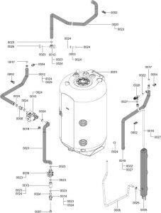
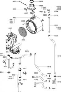
| 1 | Loading cylinder | |||
| 2 | Pipe clip Ø 18 | |||
| 3 | Sleeve G 1 | |||
| 4 | Pipe clip Ø 18 / 1.5 | |||
| 5 | Drip pan | |||
| 6 | Hose 12 x 3 l = 1300 | |||
| 7 | Sensor well with clamp G 1/2 l = 150 | |||
| 8 | Non-return valve with body 1 (fem.) x 1 (male) | |||
| 9 | Filling facility for solar heat transfer medium | |||
| 10 | Circulation pump | |||
| 11 | Spring clip DN 19 (5 pce) | |||
| 12 | Connection pipe, solar return | |||
| 13 | Shut-off valve, DHW loading cylinder | |||
| 14 | Solar connection elbow | |||
| 15 | Connection piece, solar filling device | |||
| 16 | Drain pipe, solar safety valve | |||
| 17 | O-ring 17.86 x 2.62 (5 pce) | |||
| 18 | Pipe connector | |||
| 19 | Connection pipe, solar flow | |||
| 20 | Connection pipe, central draw-off | |||
| 21 | Connection pipe, solar circuit pump | |||
| 22 | Gasket A 11.5 x 18.5 x 2 (5 pce) | |||
| 23 | Gasket A 17 x 24 x 2 (5 pce) | |||
| 24 | Gasket 23 x 30 x 2 (5 pce) | |||
| 25 | Gasket A 23 x 30 x 2 (5 pce) | |||
| 26 | Cap G 3/4 | |||
| 27 | Gasket 17 x 24 x 2 (5 pce) | |||
| 28 | Solar safety valve | |||
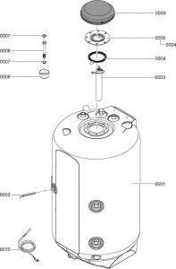
| 1 | Loading cylinder | |||
| 2 | Sensor retainer | |||
| 3 | Magnesium anode | |||
| 4 | Gasket | |||
| 5 | Flange with gasket | |||
| 6 | Cover | |||
| 7 | Gasket 23 x 30 x 2 (5 pce) | |||
| 8 | Sleeve | |||
| 9 | Flange insulation | |||
| 10 | Cylinder temperature sensor NTC 10k? | |||
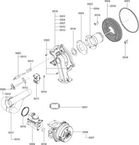
| 1 | MatriX cylinder burner | |||
| 2 | Heat exchanger | |||
| 3 | Thermal insulation block | |||
| 4 | Flue gasket | |||
| 5 | Flue gas temperature sensor | |||
| 6 | Boiler flue connection | |||
| 7 | Plug for boiler flue connection | |||
| 8 | Gasket DN 60 | |||
| 9 | Spring clip DN 25 (5 pce) | |||
| 10 | Condensate collector | |||
| 11 | Profile hose, heating return | |||
| 12 | Pipe clip Ø 18 / 1.5 | |||
| 13 | Gas pipe | |||
| 14 | Diaphragm grommet (5 pce) | |||
| 15 | Gasket A 17 x 24 x 2 (5 pce) | |||
| 16 | Condensate hose | |||
| 17 | O-rings 35.4 x 3.59 (5 pce) | |||
| 18 | Condensate hose | |||
| 19 | Condensate hose | |||
| 20 | Condensate hose | |||
| 21 | Spring clip, condensate drain | |||
| 22 | Siphon | |||
| 23 | O-ring 63 x 2.62 (5 pce) | |||
| 24 | Connection elbow, heating water return | |||
| 1 | Burner gasket (wearing part) | |||
| 2 | Thermal insulation ring | |||
| 3 | Cylinder, burner gauze assembly | |||
| 4 | Gasket, burner gauze assembly | |||
| 5 | Ignition electrode (wearing part) | |||
| 6 | Ionisation electrode (wearing part) | |||
| 7 | Gasket, burner door flange (wearing part) | |||
| 8 | Radial fan | |||
| 9 | Gas train | |||
| 10 | Burner door | |||
| 11 | Ignition unit | |||
| 12 | Gasket, ionisation electrode (5 pce) | |||
| 13 | Gasket, ignition electrode (5 pce) | |||
| 14 | Blade terminal (10 pce) | |||
| 15 | Mixture restrictor | |||
| 16 | Gas nozzle ? 13 kW/19 kW: 02 yellow ? 26 kW: 04 grey | |||
| 17 | Venturi extension | |||
| 18 | Mounting plate, thermal insulation ring (2 pce) | |||
| 19 | Gasket DN 65 | |||
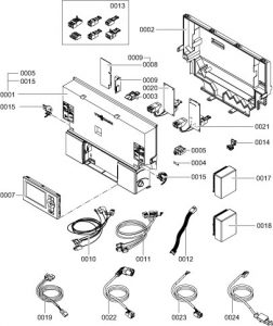
| 1 | Control unit | |||
| 2 | Control unit casing back panel | |||
| 3 | Coding card | |||
| 4 | Fuse 6.3 A (slow) (10 pce) | |||
| 5 | Fuse holder | |||
| 7 | Programming unit for weather-compensated mode | |||
| 8 | LON module | |||
| 9 | PCB adaptor | |||
| 10 | Cable harness X8/X9/ionisation | |||
| 11 | Cable harness 100/35/54/PE | |||
| 12 | Power cable, stepper motor | |||
| 13 | Mating plug (set) | |||
| 14 | Cable fixing | |||
| 15 | Locking bolts, left and right | |||
| 17 | Wireless outside temperature sensor | |||
| 18 | Outside temperature sensor (hardwired) | |||
| 19 | KM BUS connecting cable 145 | |||
| 20 | Internal H1 extension | |||
| 21 | Internal H2 extension | |||
| 22 | Connecting cable, cylinder loading pump | |||
| 23 | Power cable | |||
| 24 | Adaptor lead, collector temperature sensor | |||
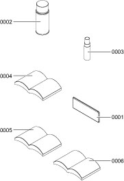
| 1 | Special grease | |||
| 2 | Touch-up spray paint, white | |||
| 3 | Touch-up paint stick, white | |||
| 4 | Installation and service instructions | |||
| 5 | Operating instructions for constant temperature mode | |||
| 6 | Operating instructions for weather-compensated mode |